Aug 10, 2022|PCB Maintenance, Repair and Troubleshooting

Circuit boards, often called PCBs (printed circuit boards), are a vital component of almost every electronic system, and they can cause massive malfunctions with a single problem. A majority of PCB issues can be attributed to human error in the manufacturing process, even as rare as that is.
Unfortunately, there is more room for human error due to the preciseness required for them to function correctly, making it almost impossible to avoid them entirely. However, there are some circuit board troubleshooting techniques that can help you fix these problems.
- Check for signs of intermittent loss of power.
- Inspect for burn marks or signs of overheating.
- Look for any malfunctioning components.
- See if there is any resulting corrosion or damage.
- Test the PCB with a multimeter.
Table of Contents
- 1 Tools Needed Before Troubleshooting Your PCB
- 2 1. Inspect Visual Elements
- 3 2. Inspect Physical Components
- 4 3. Test Individual Components
- 5 4. Test Integrated Circuits
- 6 5. Inspect The Power Supply
- 7 6. Compare a Defective Circuit Board With a Good One
- 8 7. Signal Probing
- 9 How To Dispose of Your Broken Circuit Board?
- 10 Conclusion
Tools Needed Before Troubleshooting Your PCB
Circuit troubleshooting techniques can be an intensive process that involves more tools than a simple screwdriver. In addition, the tools needed to troubleshoot and fix a PCB board might vary depending on the specific circuit board you are working on or the issue you are dealing with.
However, if you often need to handle PCB troubleshooting, you should be prepared with the following:
- Small or Fine Knife
- Microscope or Magnifying Glass (Not Needed but Helps)
- Multimeter
- Isopropyl Alcohol
- Electrical Tape
- A Soldering Iron
- Wipes
1. Inspect Visual Elements
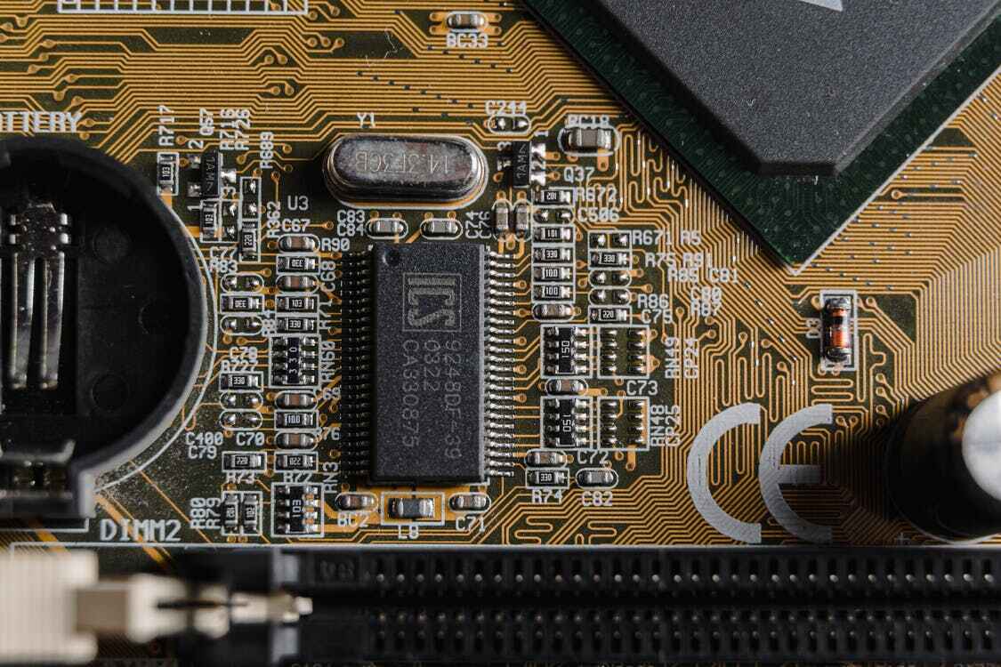
When troubleshooting circuit boards, the first thing you should do is carefully look over the circuit board. Visually inspecting the PCB helps diagnose the more obvious problems such as overheated components or bad connections.
The easiest thing to look for that would signal component error is small brown burn marks on the PCB, which can be done without much electrical knowledge or tools. Any burn marks indicate an overheated component and should be replaced.
Any bulging components or dull-looking connections are also small indicators of error.
2. Inspect Physical Components
The next step in evaluating the physical components of the PCB is an inspection with electricity connected to the circuit. Once the PCB is connected to power, one can feel different spots on the PCB to find hot spots.
Faulty connections or physical component issues usually result in spots on the PCB getting much hotter than the rest, to the point where one can feel the heat difference with their hand.
As a safety precaution, one must be careful to avoid putting both hands on the live PCB at the same time. Placing both hands on a live PCB puts one at risk of a potentially fatal electric shock crossing through the heart. Therefore, to avoid injury, you should keep one hand off the PCB during the process until disconnected from the power source.
3. Test Individual Components
Using a multimeter, testing each component is the most effective way to test PCB component failure. You can test each resistor, capacitor, and so on. You should test them individually to find out if they are working.
Each component should register at or below the stated component value, which signals that there isn’t an issue for that part. However, if the component value registers higher than the indicated value, that signals a problem.

4. Test Integrated Circuits
Testing integrated circuits is one of the most challenging parts of troubleshooting a PCB, even for professionals. This is because integrated circuits vary so heavily from one another, and there are so many specialty integrated circuits, which makes testing them an impossible task for most.
The easiest way to diagnose integrated circuits is by comparing them to a functional integrated circuit of the same kind. Comparing the functionality and behavior between two of the same circuits is much easier than diagnosing an individual integrated circuit.
5. Inspect The Power Supply
To troubleshoot the power supply, one needs to measure the voltage of the power rails with their multimeter device. The input and output values should read the expected values of the component. If not, there might be some issues.
A voltage of 0v means that there is a short circuit somewhere along the power rail, whether it’s a regulator or capacitor. In this case, the component with a short circuit will heat up extremely quickly, and one should be able to feel the heat coming off that specific part.
6. Compare a Defective Circuit Board With a Good One
Comparing two identical PCBs is one of the easiest ways to diagnose problems. However, this is only a viable option if you have two of the same PCB on hand.
The steps for this process are:
- Visually compare the two PCBs to look for any glaring issues such as burn marks or misplaced components. They should be almost identical in every way, and one should investigate any differences present to find specific problems.
- Compare the two PCBs’ behavior and functionality using a multimeter, such as the registered component values. These should be almost identical. Any differences are likely pointing at a physical component issue.
7. Signal Probing
Proper troubleshooting using signal probing is a complicated task that most non-professionals wouldn’t be capable of doing, but it is possible using a multimeter and waveform capture device. Signal probing is the process of conducting voltage tests and waveform capturing at different test points to find where the issue is occurring.
On our website, you can find more information on in-depth PCV testing methods for signal probing.
How To Dispose of Your Broken Circuit Board?
Disposing circuit boards isn’t a simple process since some components of a PCB can be recycled but not the entire thing. Knowing how to recycle circuit boards is a complicated process with varying answers to the questions surrounding it.
Conclusion
Faulty PCBs are unavoidable from time to time which makes knowing circuit board troubleshooting techniques useful. While seeming somewhat complicated on the surface, troubleshooting a PCB is a relatively straightforward process, as shown above.
Even though most PCB errors can be attributed to human error during manufacturing, you can learn how to find and fix those errors. And in doing so, you can save yourself time and money.
- Sunny Patel is the Engineering and Sales Manager at Candor Industries. Sunny is trained as a IPC-A-600 trainer, AS9100 Lead auditor, IPC CID and got his Engineering degree at the University of Toronto.
Latest entries
- February 27, 2024Technological Advancements and MaterialsHow to Order a PCB Assembly
- February 26, 2024Product Innovations and DesignReduce PCB Design Cost
- February 7, 2024Technological Advancements and MaterialsNavigating Low-Cost PCB Assembly
- January 24, 2024Quality and TestingA Guide To Automated Optical Inspection (AOI)


