Nov 6, 2023|Product Innovations and Design
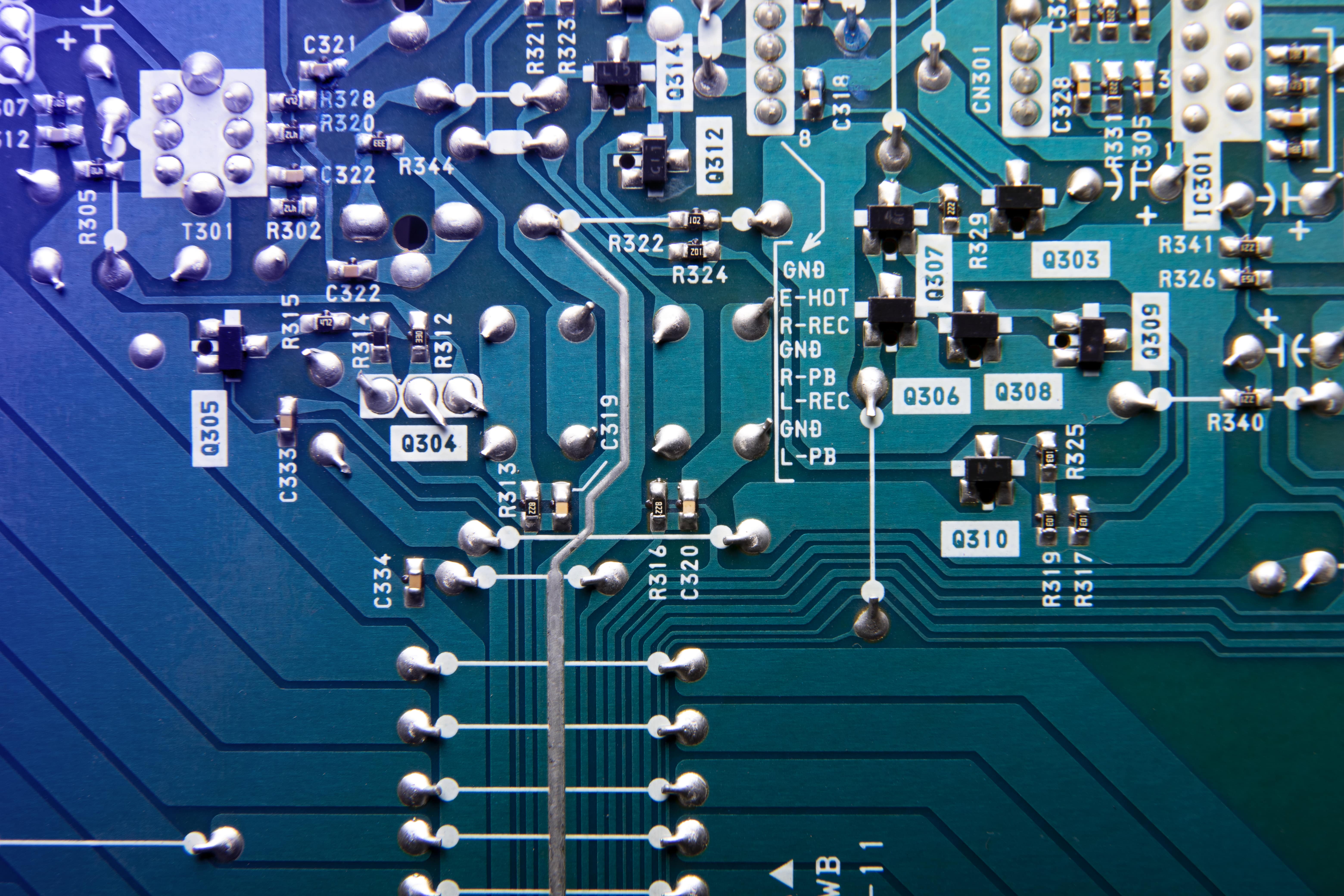
Printed Circuit Boards (PCBs) are the foundation of practically all electronic devices today, from simple toys to complex industrial machinery.
The technique of PCB routing, which connects components on the board, is critical to the creation of an effective PCB. Using effective PCB Routing Techniques can dramatically improve signal integrity and performance.
This article focuses on advanced PCB routing techniques that ensure electronic gadgets perform properly.
Table of Contents
PCB Routing Techniques

Efficient PCB routing is a nuanced art, balancing electrical requirements with physical constraints.
This is essential to understanding the role of routing and the methods to achieve optimal results. From using an auto-router cautiously to ensuring high-speed signal routing is correctly implemented, Routing or “tracking” the board requires expertise and precision.
Use Auto-router with Moderation
While auto-routers can save significant time in the routing process, relying solely on them is sometimes advisable.
Auto-routers, though automated, may only sometimes consider the intricate nuances of certain board designs. It’s a tool best used to complement manual adjustments rather than replace them.
Using auto-routers judiciously, coupled with manual oversight, can lead to more efficient routing and prevent potential issues in the design phase that may necessitate PCB troubleshooting later.
Use High-Speed Signal Routing
Modern electronics demand faster signal speeds, so high-speed signal routing has become indispensable. This technique ensures that signals are transmitted with minimal interference or distortion.
When designing electronic circuits with high-speed signals, it’s important to keep the trace widths even, watch out for impedance, and leave enough room between the traces.
Such careful considerations during the Routing board nets process prevent signal integrity issues and ensure the device functions optimally.
Make Your Traces Wider
One of the cardinal rules in PCB design is to make your traces as wide as possible. Wider traces carry more current and offer reduced resistance, enhancing performance and reducing the risk of overheating traces.
Furthermore, they are less susceptible to manufacturing issues, which means fewer interruptions and errors during the CNC routing for PCB processes.
Another significant advantage of broader traces is their ability to handle higher power levels without significant energy loss.
This ensures that the components connected by these traces receive the required voltage and current for optimal performance. Broader traces also provide better mechanical stability, ensuring the longevity and robustness of the circuit board.
In situations where space is limited, designers often face the challenge of accommodating wider traces. However, given its numerous benefits, it’s an aspect worth considering early in the design process.
The importance of trace width can’t be overstated, and the job of a process engineer often involves ensuring that such design aspects are correctly implemented for optimal functionality and reliability.
Implement Daisy Chain Routing
Daisy Chain Routing is a technique where components are connected in a series, much like links in a chain.
This method is especially beneficial when routing buses with multiple identical components, such as RAM chips on a memory module. Instead of routing from each component directly to a primary source or component, the signals are passed through each component in a sequence.
This results in a more organized and less cluttered layout, which can be crucial for boards with limited space.
The signal delay, introduced as it passes through each component in the chain, needs to be accounted for, especially in high-speed designs.
Another advantage of daisy chain routing is the potential reduction in the number of layers required on a PCB. Designers may frequently fit more connections into fewer layers by optimizing the routing path, lowering manufacturing costs and complexity.
Use Multilayer Stackup Design
In the ever-changing world of electronics, there is an urgent need for downsizing while packing in more functionality.
The Multilayer Stackup Design approach meets this desire. As the name suggests, this approach uses multiple layers in the PCB, allowing for more traces to be routed in the limited board space.
This facilitates a compact design and offers improved electromagnetic interference (EMI) shielding, as internal layers can act as a shield against external noise sources. Additionally, having separate layers for power, ground, and signals can significantly improve the PCB’s performance by reducing cross-talk and improving impedance control.
Utilizing multilayer designs requires a deeper understanding of PCB routing techniques, but the benefits of performance and space utilization are undeniable.
Implement Blind and Buried Vias
Vias are essential in PCB design, allowing connections between different layers. Traditional through-hole vias go through the entire board, but in high-density designs, these can consume precious routing space.
Enter Blind and Buried Vias. Blind vias link an outer layer to one or more inside layers but do not traverse the entire board. Buried vias join two or more inside layers and are completely enclosed within the board.
By minimizing potential interference locations, these customized vias can save significant space while also improving signal integrity. Their use, however, increases the complexity of the manufacturing process.
Therefore, while they offer clear advantages, weighing them against the added costs and manufacturing challenges is essential.
Rely on Power and Ground Plane Routing

Power and Ground Plane Routing is crucial in ensuring optimal PCB performance. Instead of using traces, entire board layers are dedicated to power and ground.
This ensures that components receive reliable power by providing an uninterrupted channel for current flow. Furthermore, having continuous power and ground planes aids in achieving a stable reference plane, which is critical for signal integrity, particularly in high-speed designs.
These planes also serve as shields, decreasing electromagnetic interference and enhancing overall signal quality. While it might seem straightforward, ensuring that the power and ground planes are appropriately separated and don’t lead to unintended short circuits is essential.
Using this technology in conjunction with modern PCB routing techniques is a proven way to improve the performance and reliability of electronic products.
Final Thoughts
Mastering advanced PCB routing techniques is critical for obtaining the best performance and dependability in the complex realm of PCB design.
Designers must navigate these issues as electronic devices continue to shrink while seeking more functionality. Each strategy has distinct advantages, from using multilayer designs to incorporating specific vias and focusing power and ground plane routing.
The goal is to understand the project’s specific requirements and to apply the appropriate solutions to achieve those objectives. As technology advances, remaining current on the latest routing practices will be critical for every successful PCB designer.
- Sunny Patel is the Engineering and Sales Manager at Candor Industries. Sunny is trained as a IPC-A-600 trainer, AS9100 Lead auditor, IPC CID and got his Engineering degree at the University of Toronto.
Latest entries
- February 27, 2024Technological Advancements and MaterialsHow to Order a PCB Assembly
- February 26, 2024Product Innovations and DesignReduce PCB Design Cost
- February 7, 2024Technological Advancements and MaterialsNavigating Low-Cost PCB Assembly
- January 24, 2024Quality and TestingA Guide To Automated Optical Inspection (AOI)


